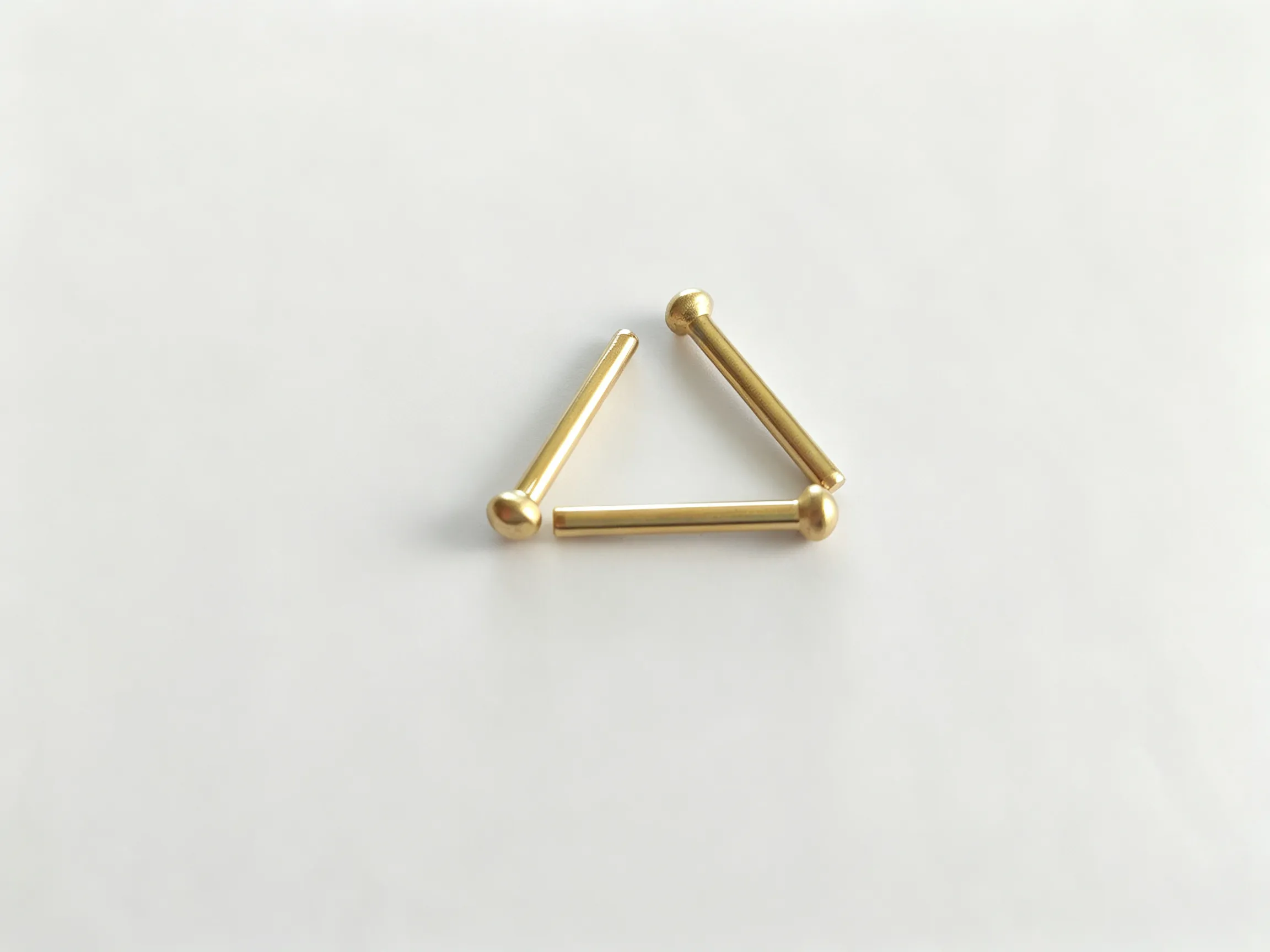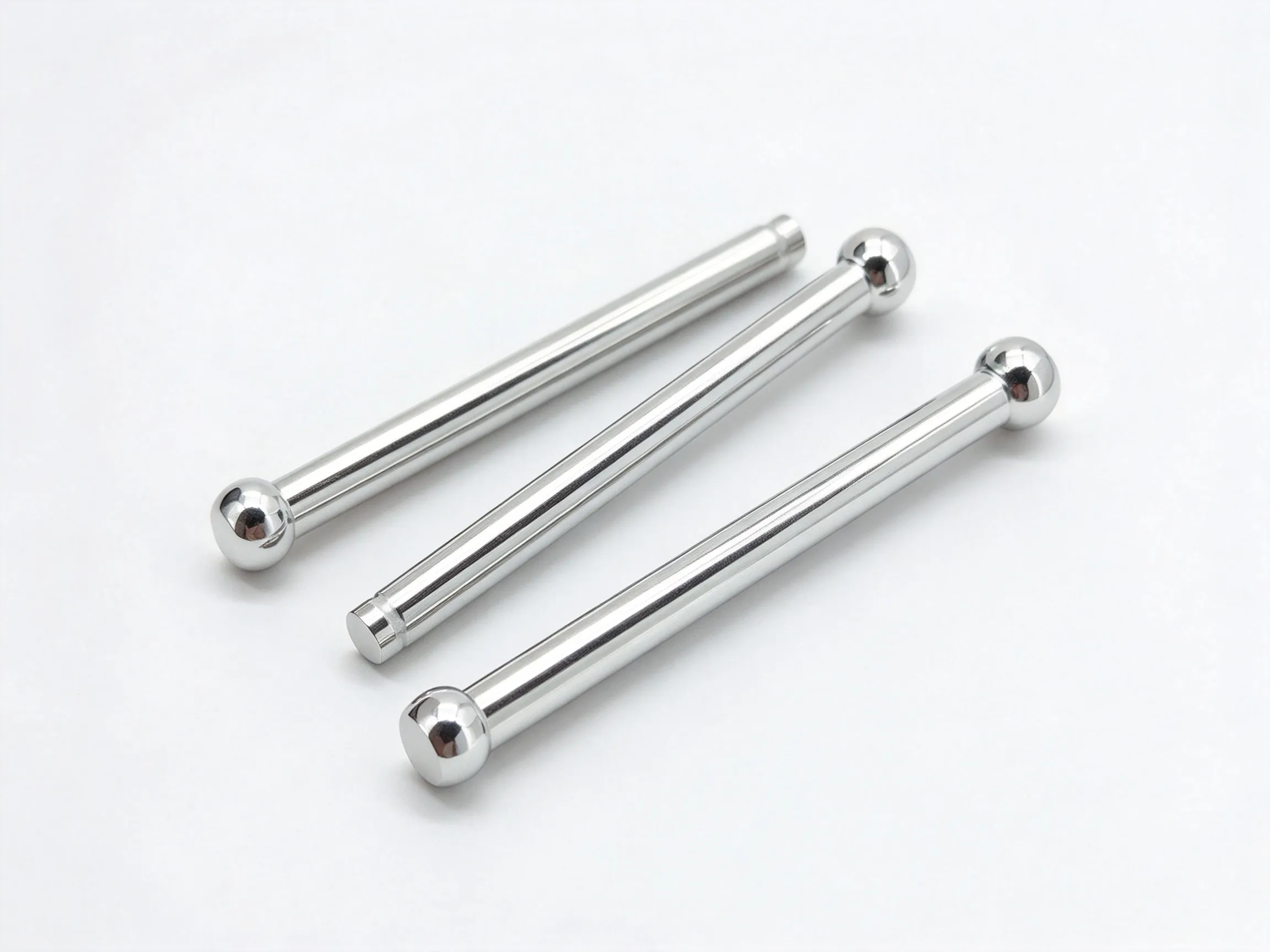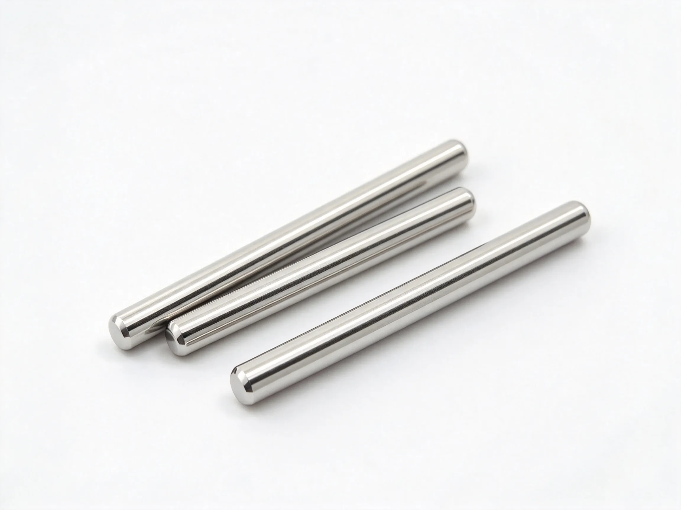


Customized hardware parts are small metal components made to a drawing or sample rather than selected from a fixed catalog. The gallery shows compact cylindrical pieces with external features, bores and stepped sections, but it is a capability view rather than a single part specification. The drawing should define the geometry, material, finish and inspection requirements for the actual component.
A drawing-led component
Start with the interface: what the part touches, what it locates, how it is retained and which surfaces carry load. Then define the dimensions that control those functions. A general note such as ‘make to sample’ is not enough when a bore, shoulder or flat face controls the assembly.
When a custom hardware part makes sense
Custom hardware parts can be considered when a standard fastener or spacer does not provide the required head, step, bore, length or material. They can also help combine several small features into one component. The decision should include the assembly volume, inspection cost and the risk of changing a part that already works.
The gallery shows several small parts with different proportions, but it does not show the production process or the tolerance capability for a particular feature. Discuss thin walls, deep bores, sharp corners and surface requirements early, because those features can affect feasibility and inspection.
What to put on the drawing
Use a dimensioned drawing with a clear datum scheme. Show the functional surfaces, the allowable radii and the areas that must remain free of burrs. State the material, temper or condition, finish and any appearance requirement. If the part must fit an existing sample, identify which dimensions are critical and which may vary.
Include the quantity and the inspection method. A first article can confirm the geometry, but production inspection needs a practical plan. For small parts, define how the bore, step or flat face will be measured without damaging the functional surfaces.
Custom hardware part requirements
- Provide a dimensioned drawing or a stable sample with critical features marked.
- Define the mating parts, fit, load path, retention and assembly sequence.
- State the material, finish, allowable burrs and surface condition.
- Agree the first-article inspection, packing method and production quantity.
Prototype and production checks
Inspect the first article against the drawing, not only against the photograph. Check the features that control assembly: bore, step, length, flatness and concentricity. Confirm that the finish does not close a small opening or change a close fit. If the part is visible, compare the surface with the approved sample under the intended lighting.
Trial the part in the real assembly before releasing the lot. Record any adjustment to the drawing so the next order is unambiguous. Keep the approved sample and inspection record together, especially when the part is small and difficult to identify later.
FAQ
Can a custom part be made from a photograph?
A photograph can start the discussion, but it is not a manufacturing drawing. Dimensions, tolerances, material and inspection requirements still need to be defined.
What if only a sample is available?
A sample can be measured and documented, but the critical features and allowable variation should be agreed before production.
How should small custom parts be packed?
The packing should prevent tangling and protect functional surfaces. Specify the method if the parts will be fed automatically or handled in bulk.
Browse the custom parts category, or compare customized parts and customized irregular parts.