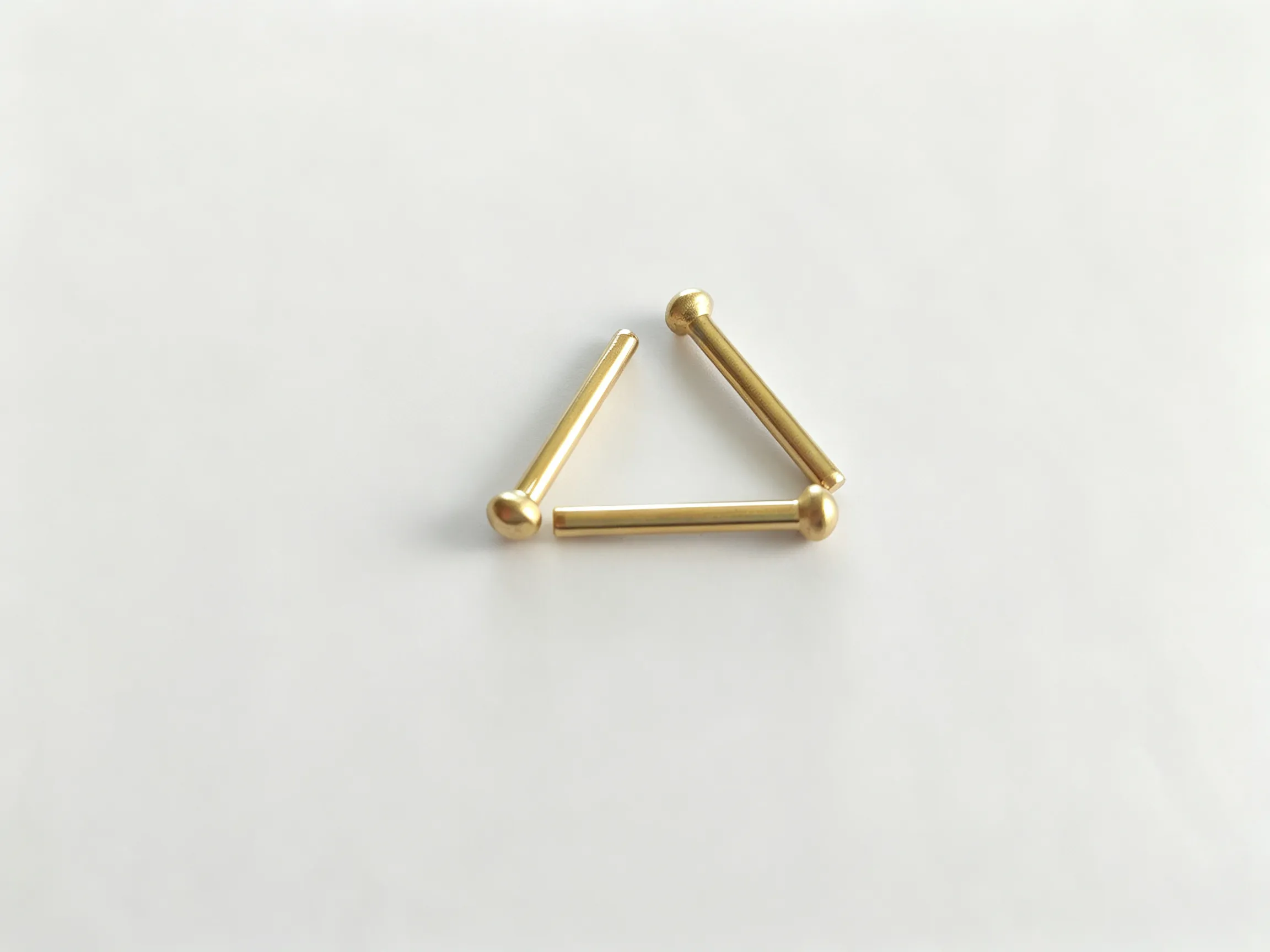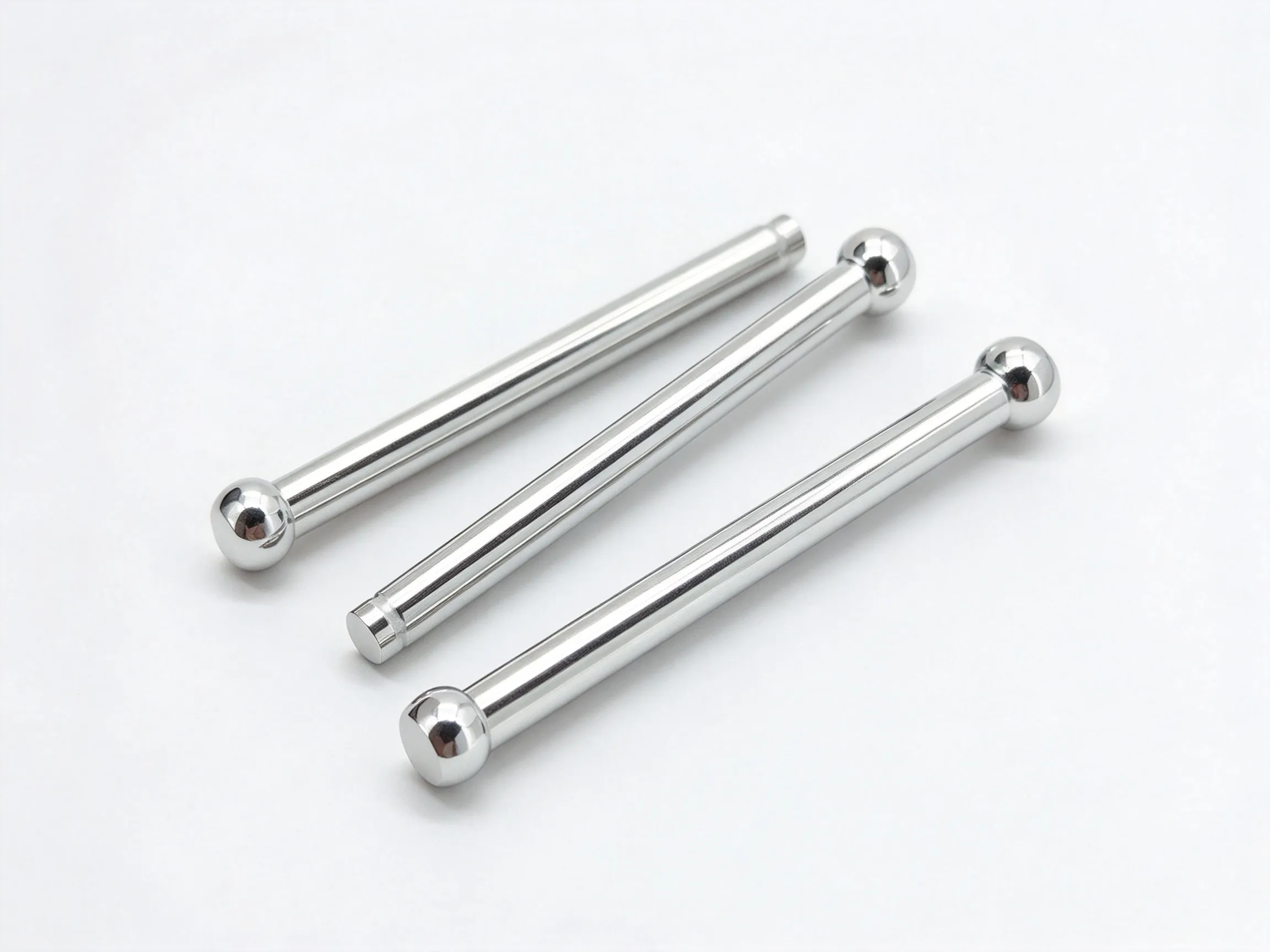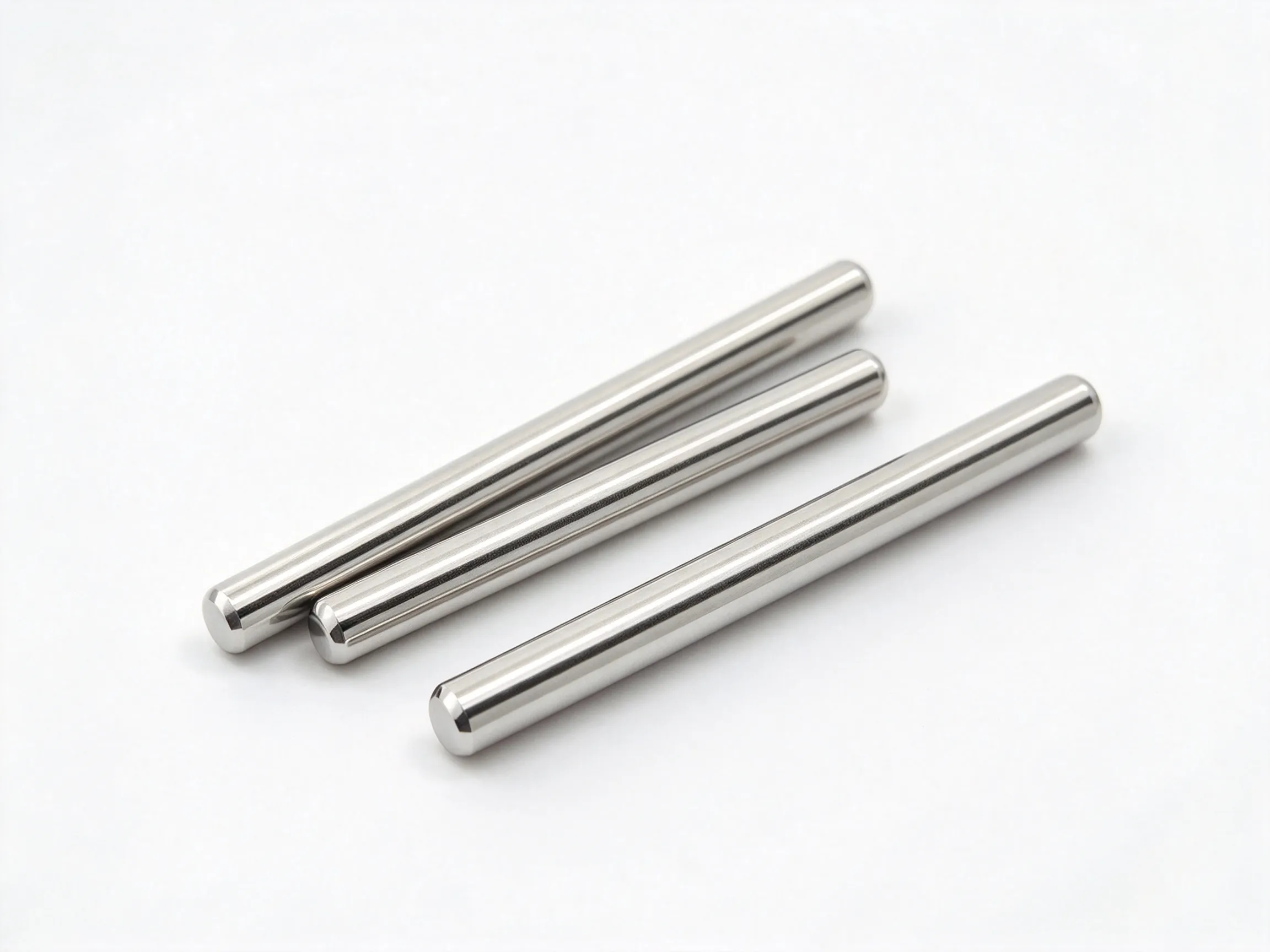


A snap-ring pin is a cylindrical pin with a groove intended to receive a retaining ring. The groove provides an axial location feature, but the pin, ring and mating bore must be designed as a set; the groove alone does not establish the retained load or the installation method.
Retaining groove and pin body
The pin body is primarily cylindrical, with a groove near one end or at a defined position. The groove width, diameter and edge radii should be shown on the drawing. A sharp groove corner can damage the ring or create a stress concentration, while an incorrect groove position can leave the ring outside its intended seat.
Axial location in shafts and assemblies
Snap-ring pins can be considered for shafts, pivot assemblies, linkage hardware and equipment where a ring limits axial movement. Check the ring type, installed orientation and the clearance needed to fit the ring. The pin should not be treated as a complete retention system until the mating groove and ring are reviewed together.
Groove and ring selection
The groove must match the selected ring, not just the pin diameter. State the ring standard or drawing, the groove dimensions and the required exposed length. If the pin is intended to rotate, confirm that the ring and groove allow rotation without catching. Do not infer an axial load rating from the presence of a groove.
Specification inputs
- Provide the pin diameter and overall length.
- Dimension the groove width, diameter and position.
- Identify the retaining ring and mating bore or shaft.
- State material, finish, quantity and inspection points.
Fit and inspection
Inspect the groove for burrs and check the pin for bending. Trial-fit the ring in the groove and confirm that it seats fully without being stretched beyond its intended range. Confirm the material and finish separately, and define any required freedom of rotation or axial movement in the assembly.
Fit the retaining ring to the actual groove before approving the pin. Confirm that the ring seats fully, does not sit on a radius and can be removed with the intended tool. Check the groove edges for burrs and the pin for straightness. If the assembly rotates, verify that the ring does not rub the housing; if it is static, confirm the axial contact faces. Record the ring specification with the pin drawing.
FAQ
Does the pin include the retaining ring?
That depends on the order. The ring should be specified separately unless the quotation includes it.
Can the groove be moved?
Yes, if the new position and the ring seat are defined on the drawing.
Is the groove a thread relief?
No. It is a retaining-ring feature when the drawing identifies it as such.
Browse the Custom Parts category, or compare thin head hexagonal nuts and customized step pins.