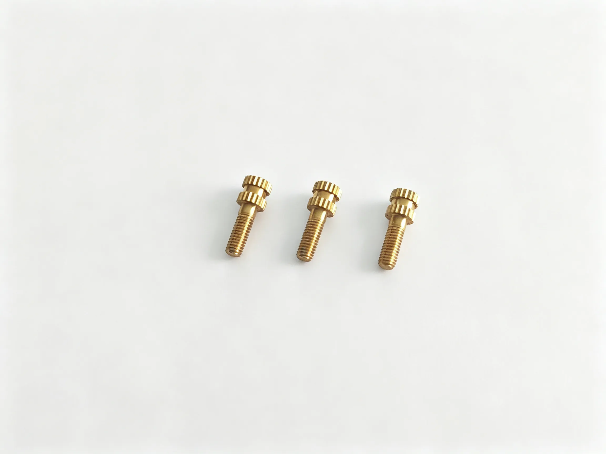


Eccentric screws are specified for assemblies that use an offset locating section to adjust the position of a mating component. Rotating the eccentric section changes its contact or locating position relative to the mounting axis. The required offset, contact profile and method of retaining the adjustment must come from the assembly drawing; a stepped outline alone does not define the adjustment.
Construction and working principle
An eccentric design has a deliberate difference between the mounting axis and the axis or working profile of its adjusting section. The thread secures the part, while the offset feature provides the adjustment. Define both axes, the reference face and the required angular orientation. Confirm which portion turns during adjustment and how the final setting will be secured.
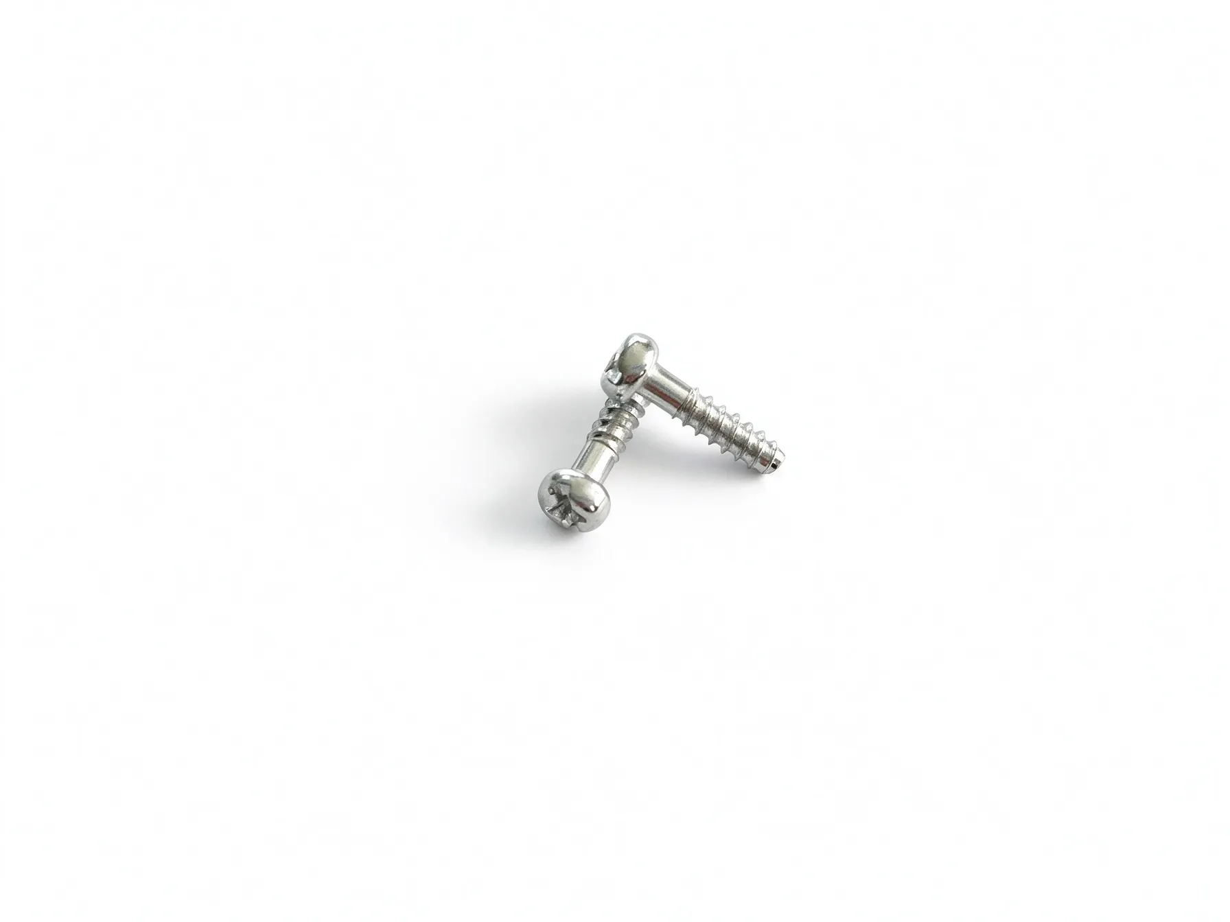
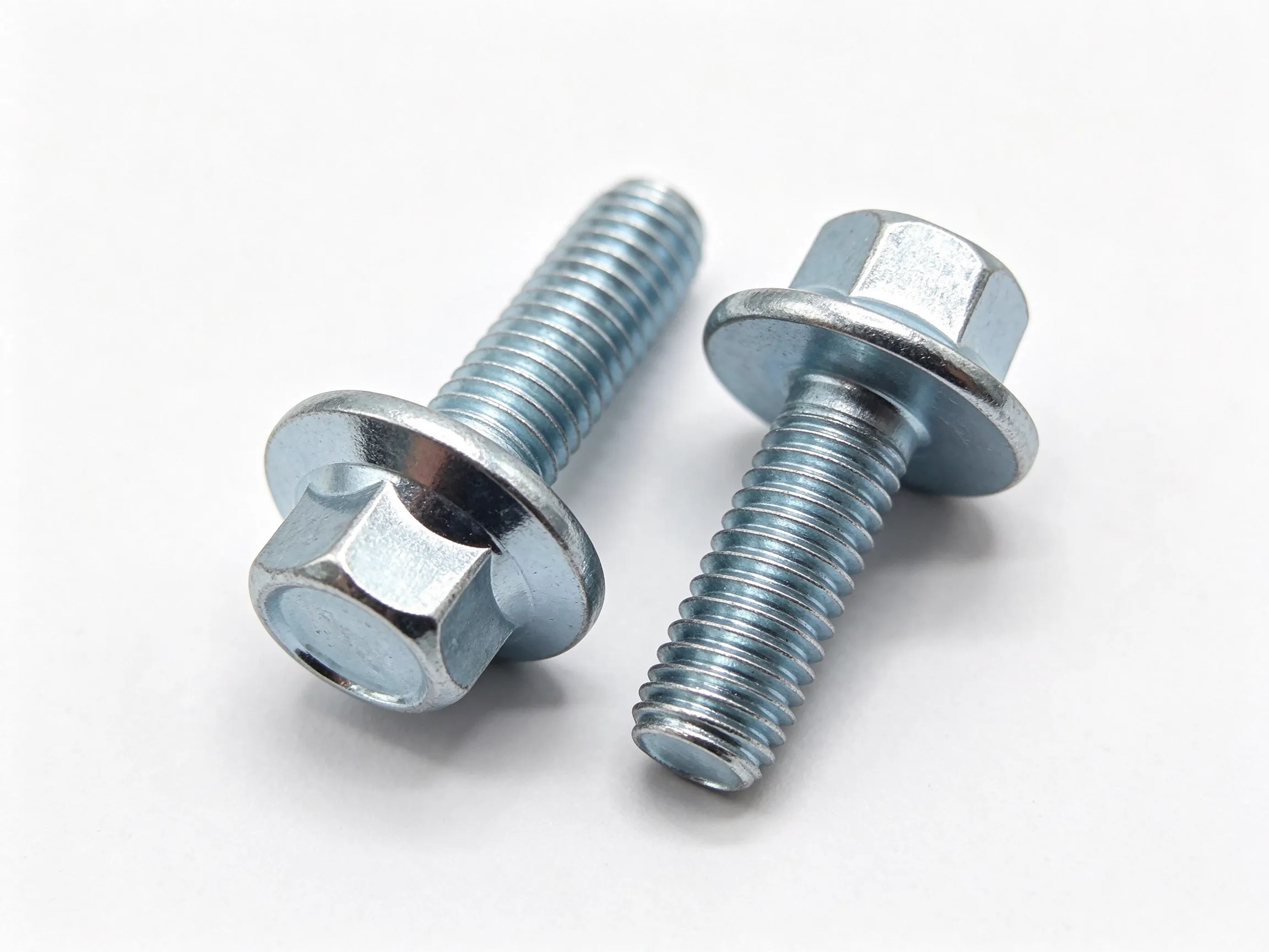
The gallery shows threaded parts with different flange and wrenching profiles. It does not provide a measured eccentricity or a dimensioned cam profile. Confirm the selected configuration against a drawing or physical sample before treating it as a particular adjustment mechanism.
Typical applications
Eccentric screws can be considered for guide adjustment, linkage alignment, fixture setting and mechanisms that need a small positional correction. Their suitability depends on contact load, available rotation and the way the setting is retained. Describe the component being moved and the adjustment direction. A mechanism intended for occasional alignment needs a different review from one that moves repeatedly during service.
Eccentric adjustment versus a concentric shoulder
A concentric shoulder establishes a locating diameter around the mounting axis. An eccentric feature deliberately offsets the working position from that axis. Rotating a concentric shoulder does not create the same lateral adjustment. If the drawing only shows changes in diameter without an offset reference, resolve the geometry before selecting the eccentric version.
How to specify an eccentric screw
- Identify the mounting axis, offset feature and required eccentricity.
- Dimension the thread, flange, locating section and axial seating faces.
- Show the mating component, adjustment direction and available rotation.
- State contact load, setting-retention method, material, finish and quantity.
Material, finish and installation checks
Review material and surface treatment for the contact condition and service exposure. A bright surface does not establish hardness, wear resistance or substrate. Check the functional profile after finishing. On a representative assembly, verify the movement across the intended adjustment range, surrounding clearance and the final secured position.
Do not use a generic screw torque as evidence that the adjustment will remain fixed. The thread engagement, contact arrangement and retention method need to be reviewed together, particularly when service loads can rotate or displace the adjusting part.
FAQ
Is every stepped screw an eccentric screw?
No. A step is a change in diameter. Eccentricity is an intentional offset between reference axes or a working profile.
Can the adjustment range be read from the photograph?
No. The range depends on the offset geometry, permitted rotation and mating component. Provide those details on the drawing.
What should be included in an RFQ?
Send the dimensioned drawing or sample, adjustment requirement, mating-part details, load, retention method, material, finish and quantity.
Browse the eccentric screws category, or compare stepped locating screws and step positioning pins.